After a long period, PySLM version 0.6 is released. This coincides with the intensity of commitments as a new academic at the University of Nottingham over the past year. The release has mainly focused on improvements and enhancements to the underlying codebase rather than the addition of entirely new features. There are several substantial changes to the underlying dependencies that contributes some improvements and performance throughout which PySLM users will benefit from.
Dependency changes
With the release of ClipperLib2 library, additional python bindings were exposed and released as a separate library in the PyClipr. These were created using the PyBind11 headers and provides the core functionality required to performing offsetting and clipping of path segments and hatch vectors. There are no substantial feature improvements inherited from the change, but a noticeable performance improvement can be observed. Another benefit is that PySLM does not require compilation via cython and is now a full source distribution available via PyPi repositories.
Another significant dependency change is the use of the manifold mesh Boolean library. This offers a substantial improvement to mesh manipulation operations, that are fundamental to successful support generation for use in metal L-PBF. The library provides robust intersection of water-tight meshes, that is also computationally efficient when compared to the prior PyClipr library which was based on the clipr library from over a decade ago. This significantly improves the quality of the volumes generated in BlockSupportBase and those derived from these such as those with the GridTrussSupport that provide perforations and teeth for metal L-PBF. Additionally, this removes an additional dependency that requires maintenance by myself, and is more cross-platform that what can be offered by the previous PyClipr library.
Further incremental changes, that will not affect users is migration to the Shapely 2.0 library and also Trimesh 4.0, which required some internal changes to maintain compatibility.
Support Generation Improvements:
The support generation has been improved to be more robust and reliable compared to the initial release in version 0.5.0. Further robustness checks are implemented in the ray-tracing method developed in version 0.5, for identifying correctly the support projection height maps which are used to identify boundaries of the support volume. Further use has been explored in applied research by TWI – see open access paper (An Interactive Web-Based Platform for Support Generation and Optimisation for Metal Laser Powder Bed Fusion) by Dimopoulos et al.
By default all BlockSupport‘s have smoothed boundaries by the use of spline fitting, which was previously only applied on self-intersecting supports. Smooth boundaries significantly improve the quality of the final GridBlockSupport, because the perforated grid truss skin can more smoothly conform to the boundary of the support volume.
Smoothed boundaries generated for all SupportVolumes for a complex part: including both self-intersecting supports and those only connected to the build-plate
As a recommendation to users, care must be taken to not smoothen the boundaries too much or these will not correctly conform to the original geometry causing the ray-projection algorithm to fail. A recommending starting point for the spline simplification factor is between 5-30, but is dependent on the relative part scale. Coinciding with the use of the manifold3d library, there is an appreciable improvement in the speed for generating the support volumes.
Another improvement is the more configurable parameters for Grid Truss Support generation. This includes further enhancement and control over the perforated teeth, across both upper and lower support volume surfaces. These are fully customisable by a user function, which ensure that a repeating shape is conformed in 3D across the surface profiles of the support volume.
Finally, a significant enhancement is correctly pre-sorting the scan vectors within the sliced support regions to take advantage of the line segments when scanning by the beam source. This significantly improves build productivity by minimising jumps across adjacent segments and ensures that the galvo-mirror movement remains mostly in the same direction.
A layer showing the order of scanning across all grid truss support generated for a complex topology optimised part. Jump distance is a total of 2056 mm with a total scan vector length 1377 mm.
Documentation Improvements
Further improvements to the inline documentation have been included alongside improvements and examples that are now provided on readthedocs. These provide basic information and guides for using PySLM, some of which is consolidated from these blog entries to aid new users using the library. Over time these will be further enhanced and amended to support researchers and users wishing to use PySLM in their work.
Conclusions & Change Log
The release has taken a while to release, but overall has received a level of polish and refinement that helps the release find use amongst more in commercially vested R&D projects and academic research. There are other developments still in the pipeline but much focus was on providing a long-term stable release for users. The full changelog can be found here.
Following on from the previous post in Part II, this post will detail the methodology for ‘Grid Block’ support generation, which is one of the most commonly utilised support structure used especially in the selective laser melting process.
The definition of a volumetric block support region is illustrated shown below for an example topology optimised bracket. These are projected volume regions that extend vertically dowwards from the original overhang surface, that conforms exactly with the input mesh.
Volume Block Support Structures extruded from overhang un-supported regions for a topology optimised bracket
Prior to starting this work, two approaches for generating ‘block‘ based support structures seem to exist. However, these approaches did not seem satisfactory especially when it came to their use using cost models.
The first approach identified, typically employed in FDM based processes, obtains the support or overhang regions and then generated a 2D polygon region that is the flattened or projection of this surface. The polygon is incrementally generated for each slice layer and a combination of boolean operations and offsetting operations are used to detect self intersections with existing geometry to modify its shape. It’s a robust method and can generate support features to aid manufacturing. The limitation of this approach is it cannot generate a volume, or an explicit mesh geometry. Rather a discretionary of the geometry containing slices representing the region with a sparse infill.
The second approach would appear to voxelise or generates a levelset of the geometry. Under support regions, the voxel grid is filled to create the in-fill support regions. The volume region can be re-constructed into a support structure and a truss structure can be generated inside. This method is not able to generate clean meshes of the support volume and requires a discretisation of the original geometry.
The following method proposed uses a hybrid mesh approach in order to generate clean meshes using fairly conventional boolean CSG library. The actual support structure generated uses relies on using 2D polygons to generate complex features such as perforation holes or structures.
Overall Support Module Structure Summary
The overall support module, in its current state for version 0.5, is split into the following structure. The generation of supports is performed by a utility ‘generator‘ class BaseSupportGenerator and incidentally their derived classes:
These classes perform the overhang and support analysis to extract the overhang surfaces. From the overhang surface, the support volumes are then generated using these to provide the inputs used to generate specific support objects that may have a specific style. For the objects representing the actual support structures, and regions, these are split into the following classes:
SupportStructure – Base class defining a part’s surface requiring support
BlockSupportBase – Generates support block volumes for providing a region to support
GridBlockSupport– Generates a support with a grid trust suitable for SLM
Overhang and Support Area Identification
The first step, widely available amongst all CAD and pre-processing software is overhang identification. Determining the face angles is a trivial process and in PySLM may be obtained using the following function pyslm.support.getSupportAngles. The function takes the trimesh object and calculates the dot product of the surface normal across the mesh. Upon obtaining the dot product, the angle between the vectors is calculated and for convenience is converted from rads to degrees. Further explanation is provided in a previous post.
# Normal to the Z Plane
v0 = np.array([[0., 0., -1.0]])

#Identify Support Angles
v1 = part.geometry.face_normals

# Calculate the angle (degrees) between the face normals and the Z-plane
theta = np.arccos(np.clip(np.dot(v0, v1.T), -1.0, 1.0))
theta = np.degrees(theta).flatten()
Upon obtaining the surface angles, the overhang mesh regions can be extracting from the originating mesh, similar to that used in pyslm.support.getOverhangMesh. A comparison to a threshold overhang or support angle is made and used as a mask to extract the face indices from the mesh in order to obtain a new mesh. It is common that the overhang regions are disconnected. These can optionally be split using trimesh.split , which uses the internal connectivity of vertices in the mesh in a connected-component algorithm to isolate separate regions.
# Extract a list of faces that are below the critical overhangeAngle specified
supportFaceIds = np.argwhere(theta > 180 - overhangAngle).flatten()

# Create the overhang mesh by splitting the meshing when needed.
overhangMesh = trimesh.Trimesh(vertices=part.geometry.vertices,
                               faces=part.geometry.faces[supportFaceIds])
if splitMesh:
    return overhangMesh.split(only_watertight=False)
Splitting the mesh is far more convenient in terms of processing the support structures. It also improves the performance by reducing the projected area when performing ray intersections to identify an approximate volume.
Providing a robust method for obtaining the projected support volume is not a straightforward task, especially without sophisticated boolean operation tools. Through some experimentation with the given software libraries available, the following process offered a satisfactory result without a reasonably long computational cost.
Summary of method
The following operations are performed to generate block supports:
Support regions (3D mesh surface) are separated into meshes
Each support region mesh is flattened into a polygon and the contour is offset
Surface region is extruded to z=0
Intersection test using a Boolean Mesh Intersection operation is performed to check if self-intersection with part
If self-intersection exist a ray-projection height map is created
Side surfaces are removed from the intersection
Ray projections are made separately on upward facing and downward facing faces and the height map is built up
The gradient of the height-map is used to separate regions are extracted outlines of separate support regions
For each support region:
Triangulate the polygon regions into a mesh
Rays are projected along Z in both directions from the mesh vertices to obtain the required extrusion height
The triangulated polygon is extruded in both directions using the extrusions heights with an offset
The extruded prisms are intersected with the original part mesh to obtain the final support volumes.
Inside the function, the support regions are flattened into a polygon BaseSupportGenerator.flattenSupportRegion. This method extracts the outline or the boundary of the support region and flattens via projection by setting z=0along the coordinates. The paths are then translated into Shapely.Polygon objects.
""" Extract the outline of the overhang mesh region"""
poly = supportRegion.outline()

""" Convert the line to a 2D polygon"""
poly.vertices[:, 2] = 0.0

flattenPath, polygonTransform = poly.to_planar()
flattenPath.process()

flattenPath.apply_translation(polygonTransform[:2, 3])
polygon = flattenPath.polygons_full[0]
The polygon region is generated it provides the elementary building block for generating a support structure. This can be used to offset to prevent collision with self intersecting features. Internally, offsetting is useful to perform to regions so that any self-intersections with the geometry are clean.
Region Extrusion and Self-Intersection Check
The first pass of the proposed algorithm requires performing a boolean intersection to identify if there are any self-intersections. The polygon regions require extrusion. Near-net shape extrusion is accomplished using a custom function pyslm.support.extrudeFace. Unfortunately, this is not available within Trimesh, so instead it had to be implemented manually. This function extrudes a region of connected faces within a polygon, to set position or each individual face offset by an extruded distance.
# Extrude the surface to Z = 0
extrudedBlock = extrudeFace(supportSurface, None, 0)

# Extrude a triangle surface (Trimesh) based on the heights corresponding to each surface triangle
extrudedBlock = extrudeFace(surface, None, heightArray)
Having obtained an extruded prism from the support surface, a self-intersection test is performed with the original part. If no self-intersection takes place, this means the support structure has connectivity with the build platform. Under this situation, this drastically simplifies the number of steps required.
Example of an extruded mesh used for self-intersection tests
The intersection test requires a Boolean CSG operation. Quickly profiling a couple of tools available, from experience trying available solutions, the Cork Library was found to be both a reasonably accurate and high performance tool for manifold 3D geometries (i.e. those already required for 3D printing). The Nef Polyhedra implementation in the CGal library is renowned to be an accurate and robust implementation but slow. Due to these reasons, the PyCork library was created to provide a convenient wrapper across all platforms to perform this.
# Below is the expanded intersection operation used for intersecting a mesh
# cutMesh = pyslm.support.geometry.boolIntersect(part.geometry, extrudedMesh)

meshA = part.geometry
meshB = extrudedMesh

vertsOut, facesOut = pycork.intersection(meshA.vertices, meshA.faces, meshB.vertices, meshB.faces)

# Re-construct the Trimesh
cutMesh = trimesh.Trimesh(vertices=vertsOut, faces=facesOut, process=True)

# Identify if there is a self-intersection
if cutMesh.volume < BlockSupportGenerator._intersectionVolumeTolerance: # 50
    # The support does not self intersect
else:
    # The support intersects with the original part
In the situation that there is no intersection (or the volume is approximately zero), the support volume simply extrudes towards the build-plate. If a self-intersection occurs with the part, further calculations are required to process the block support.
Self-Intersecting Support Structures
If the support-self intersects this is far more challenging problem to deal with. Through a lot of experimentation, the most reliable method determined involved using a form of ray-tracing to project the surfaces down. This has two benefits:
Separating support regions across different heights
Providing a robust method for generating cleaner support volumes with greater options to customise their behaviour
The ray projection test is useful generally, as it can also be used to provide a support generation map for the region, as shown in the previous post.
Originally the ray projection method was done using Trimesh.Ray, where rays are projected from each support face at a chosen ray projection resolution BlockSupportGenerator.rayProjectionResolution. A grid is formed with seed points for the rays and these are projected upwards and downwards onto the previous self intersected support mesh. The ray intersection test is performed on upward facing surfaces extracted from the existing intersected mesh, in the previous region.
Later this was updated to use a GLSL GPU process for identifying this at a much higher resolution at significant reduction in computational cost as discussed in a previous post.
From the ray projection map, individual support block regions can be separated based on taking a threshold of the image gradient, using the gradThreshold function. Using simple trigonometry, the threshold to determine disconnected regions in the intersecting support are determined by the resolution of the ray projected image and the overhang angle, with an added ‘fudge-factor‘ thrown in.
Regions are separated based on this threshold using the isocontour method offered in Skimage’sfind_contours function. This is useful because it can identify supports regions connected only to the build-platform (desirable) and self-intersecting regions with the original part. Additionally, self-intersecting support regions with difference heights can also be isolated. These are useful in some marginal scenarios, but were more simpler methods breakdown.
Ray Projection Map of support region used for identifying and separating support regions. Note the relatively high resolution used by using the GPU Projection Map Technique
A projected region extracted by extracting the contour isolevel from the projection map (left). The outline is transformed into absolute coordinate system for the part.
The regions are identified by taking a threshold based on the choice of overhang angle using the BlockSupportGenerator.gradThreshold.
def gradThreshold()
    return 5.0 * np.tan(np.deg2rad(overhangAngle)) * rayProjectionDistance

# Calculate the gradient of the ray-projected height map for the support region
vx, vy = np.gradient(heightMap)
grads = np.sqrt(vx ** 2 + vy ** 2)

# A blur is used to smooth the boundaries
grads = scipy.ndimage.filters.gaussian_filter(grads, sigma=BlockSupportGenerator._gausian_blur_sigma)

"""
Find the outlines of any regions of the height map which deviate significantly
"""
outlines = find_contours(grads, self.gradThreshold(self.rayProjectionResolution, self.overhangAngle),
                            mask=heightMap > 2)

# Transform the outlines from image to global coordinates system
outlinesTrans = []
for outline in outlines:
    outlinesTrans.append(outline * self.rayProjectionResolution + bbox[0, :2])
Once the outlines are obtained. The boundaries are created into polygons, offset, optionally smoothed and then translated into triangular meshes using triangulate_polygon. Care must be taken when using spline-fitting to smooth the boundary as this can result in profiles not conforming to the original overhang region. The triangulation procedure internally can use either the earbox-cut algorithm or constrained Delaunay via the Triangle Library. The points of the polygon mesh are projected upwards and downwards on a subset of the previous intersected mesh to located the approximate volume before performing the final boolean operation.
# Create the outline and simplify the polygon using spline fitting (via Scipy)
mergedPoly = trimesh.load_path(outline)
mergedPoly.merge_vertices(1)

# Simplification and smoothing of the boundary is perform to provide smoother boundaries for generating a truss structure later.
mergedPoly = mergedPoly.simplify_spline(self._splineSimplificationFactor)

outPolygons = mergedPoly.polygons_full

"""
Triangulate the polygon into a planar mesh
"""
poly_tri = trimesh.creation.triangulate_polygon(bufferPoly, triangle_args='pa{:.3f}'.format(self.triangulationSpacing))

# Use a ray projection method onto the original geometry to identify upper and lower boundaries

coords = np.insert(poly_tri[0], 2, values=-1e-7, axis=1)
ray_dir = np.repeat([[0., 0., 1.]], coords.shape[0], axis=0)

# Find the first location of any triangles which intersect with the part
hitLoc, index_ray, index_tri = subregion.ray.intersects_location(ray_origins=coords,
                                                                    ray_directions=ray_dir,
                                                                    multiple_hits=False)
The same process is repeated, and an extruded prism is generated based on the ray-projection regions. Simplification of the interior triangulation is done in order to minimise the time to perform the intersection.
The prismatic mesh extruded based on the ray-projection distances obtained.
The prismatic mesh extruded based on the ray-projection distances obtained.
Finally, to obtain the ‘exact’ conforming intersected mesh, once again this is intersected with the previous mesh to obtain the final support volume region conforming to the original geometry.
As it can be observed, there are many steps to obtain the exactly conforming support volume with the original mesh. For the majority of most geometries that would be printed, this method is adequate, although not full-proof. There are a few cases where this algorithm will fail due to the use of a ray projection algorithm and relying on line-of-sight. For example, a continuous spiral or 3D helix structure with large connected surfaces will not be identifiable from the support generation algorithm. Without developing a specific mesh intersection library, it is difficult to identify alternative ways around this. Admittedly this is beyond my ability.
Following on from the previous post looking at methods for identifying overhang regions for use in support structures, the ray projection method approached felt unsatisfactory, especially from a performance perspective. This is used as part of the support generation module when determining self-intersecting support structures with the part and for generating the initial 3D conformal volumetric block supports alongside the boolean operations.
The depth projection map is used to firstly identify the unsupported regions, using the selecting overhang angle. These regions are then intersected with the existing part to detect self-intersection and those regions that are only attached to the build-plate. This is later determined by seperate support volumes by identifying large differences between the region. This will be later explained in greater detail in a following post.
The in-built ray projection method used by Trimesh used the RTree library internally. Alternatively, PyEmbree, based on Intel’s Embree library can be used, although extremely efficient for purposes of RayTracing application, it unfortunatly cannot provide an accurate ray intersection for the purposes of generating support structures. The Rtree method unfortunately is not particularly high performance, even using a spatial tree-index structure for the acceleration structure and is also not multi-threaded. Increasing the resolution spatially has a performance cost O(\Delta x^2) and this is ultimately linear based on the number of ray search. Increasing the complexity of the mesh and throwing more triangles into the mix, further compounds the computational effort. Anecdotally, this mirrors the same issue with some voxelisation methods based on ray-tracing methods such as the one proposed by A. Aitkenhead .
The previous solution worked, especially on relatively simple geometries, but was unsatisfactory even with a boolean intersection with the a mesh created projecting the support surface downwards.
Following a foray into learning about GPU computing using GLSL shaders and also OpenCL and two years ago, there seemed a practical approach to solving this. This similar approach has also been recently used for generating signed-distance fields for meshes for use in Deep Learning geometries in PyTorch3D, shared on their Github repo. Their approach projects points close to the mesh and then using the surface normals and native depth occlusion tests available in OpenGL can project an approximate signed distance field – this has now become abbreviated (SDF) in literature.
Methodology
For illustrating the method, the existing geometry of a topology optimised bracket to demonstrate a relatively dense triangular mesh, the part is orientated in the following fashion.
Topology optimised bracket used as an example for identifying support regions using a ray projection method.
Like the previous method, we do not necessarily have to work with the overhang region mesh.
The extracted overhang mesh obtained from a Topology Optimised Bracket
In the method, one simply needs to rasterise the Z-position of the surface of the mesh and discard hidden surfaces in order to emulate a single-hit ray projection approach. Using OpenGL GLSL fragment shaders this can be done by taking the orthographic projection of the model and then rasterising the Z position of each fragment (pixel) across each triangle.
The occlusion test is natively built into the standard 3D Graphics pipeline, which essentially emulates the ray-tracing approach. As trivial as it may sound, programming this in Python didn’t come easy. It required changing the framebuffer object (images that the triangles are rendered). Another subtle trick required is defining the the vertex colour Vertex Buffer Object (VBO) with the z-coordinates for its corresponding triangle vertex. The Z ‘colour’ value is then natively interpolated across each triangle during rasterisation and based on the depth-test performed automatically by OpenGL, only the most closest value remains, with other fragments in discarded. The GLSL fragment shader is shared below:
The desired resolution of the ray-projection map is simply changed by setting the Window size or the underlying framebuffer size. The implementation is based on Vispy library, which provides access to many low-level building-blocks for creating OpenGL applications via its supporting library Glumpy. In this implementation, the vispy.app.Canvas is redefined , including the GLSL Shader Programs, OpenGL transformation matrices (Model-View-Projection MVP matrices) and also the framebuffer properties and OpenGL states required for rendering the mesh.
Once complete, the output from the framebuffer can then be transferred to a numpy array for further processing. Very large resolutions may be achieved with little performance impact using GPU computation. These high resolution ray-projection maps are extremely important for accurately capturing the overhang regions and ensuring that each support structure is correctly attached and conforming to the part’s geometry.
Output generated from Vispy to rasterise the Z-position to emulate the ray-projection method. Note the high resolution attainable using this approach. The only limitation is the size of the GPU framebuffer.
Another advantage of capturing the effective ray projection using this means, is the background is clearly identified easing segmentation. Upon obtainingt the ray-projection method, the overhang regions can be identified as using the gradient of the ray project map, as discussed in the previous post. Gaussian convolution kernel may be applied on the thresholded image, so that the boundaries can be smoothed before extracting boundaries.
Overhang angles obtained based on the gradient across the depth image and a threshold.
The boundaries may then be obtained using by extracting the isolevel from the thresholded image accordingly using
import skimage.measure
import skimage.filters
import pyslm.visualise

# The background is masked using the alpha channel from the framebuffer. A gaussian blur is applied onto the overhang image to smoothen boundaries
ov = overhang * c.rgb[:,:,3]
ov = skimage.filters.gaussian(ov, sigma=8)

plt.imshow(ov > 0.5)

# Locate the boundaries using marching-squares algorithm
contours = skimage.measure.find_contours(ov.T, 0.5)

# Create the paths for manipulation later
fig = plt.figure()
triPath = pyslm.support.createPath2DfromPaths(contours)
The resultant boundaries are shown below.
Boundaries extracted from the overhang regions. The boundaries may be simplified later.
Conclusions
Despite the simplicity of this method, it is not readily used in many areas despite its advantages. The problem with the method is often setting up a suitable OpenGL environment and back-end in Windows and Linux environments, especially in conjunction with using Python. This resulted in many delays in the release of PySLM v0.5, but these have been resolved across all platforms.
This approach provides a very fast and efficient method for performing ray-projection tests especially resolving this at high resolutions for complex meshes harnessing the power of GPUs. Having a complete rasterised image with polygon boundaries provides the ability to offset and generate smoother support regions later.
PySLM 0.5 has had a long incarnation. It has been waiting in anticipation for the past year and delayed due to challenges with the coding and ensuring cross-compatibility. It is an exciting release and a testament to the relative maturity of the project. Already, it is fantastic to observe that it is providing a great positive contribution and benefit to the research in the Additive Manufacturing community. Once again, I wish to personally thank everyone’s support developing this along the way.
The highlight of the 0.5 release is the addition of the new Support Module. The Support Module provides the building-blocks and the infrastructure to identify and extract support volumes, and generate their support structures based on meshes provided as input. The module has been in development in the background for over two-three years and finally, reaching a level of maturity that was in a position to release into the public.
The tools include the usual and standard technique of extracting overhang surfaces, edges and points based on the on their facial connectivity which was discussed in a previous post. These surfaces are used as the input in a ray-tracing approach for identifying precise volumetric block support structures as shown above. Unlike most implementations available externally, these conform to the boundaries of the part, utilising a new boolean CSG library PyCork, which provides a cross-platform Python implementation of the Cork Library. Due to limitations in existing CSG approaches available, a fast GPU based ray-trace approach is utilised to project identified support surfaces and create a high-resolution projection height-map to locate self-intersections like below. Furthermore, these provide additional flexibility to create alternatives approaches, such as those suitable for other manufacturing processes e.g. point-support structures (e.g. in SLA) or tree like support structures.
GPU Generated Depth Projection Maps
Each support surface identifies self-intersections with the original part and those with the build platform. The regions are segmented using an image processing technique based on an overhang tolerance and transformed into polygon boundaries. Simplification is necessary and use a combination of the Douglas-Peucker algorithm within scikit image’s approximate_polygon function and b-spline fitting tool available in Scipy. The boundary simplification is useful to alleviate issues when encountering sharp features extracted from jagged edges in the support regions.
These volumetric regions provide the foundational elements for constructing sophisticated support structures, especially those used within SLM systems. To maximise productivity, provide greater control over controlling distortion due to residual stress, grid-truss based support structures have been utilised for over a decade in SLM. Unfortunately, I have yet an to come across a known implementation that exists both in literature nor open-source code to generate these structures. Below is an example of conformal grid-truss geometry generated for a complex topology optimised bracket component.
In the implementation, the grid truss structure is generated by taking cross-sections throughout the support volumes and using a geometric polygon operations offered by the ClipperLib. The truss is formed by generating hatch lines that are offset and union to create a truss. This approach provides flexibility to design different structures. Afterwards, 3D triangular meshes are generated from the polygon boundaries which are mapped back onto the original support volume. Doing this efficiently is challenging given the potential size and number of support structures that can be generated.
Under own testing, the implementation is reliable for most geometries, although there are few known cases where the algorithm will not work. It is acknowledged that the support module is not intended to be a direct replacement for commercial software, rather, provide a working reference that researchers and general users can understand, adapt and utilise in their own work/research or part of a pipeline.
The installation of PySLM 0.5 has soft-dependencies for using the support module due to the additional algorithms required. Please, ensure that these are all installed and that there is a working OpenGL 2.1 installation (via Vispy and PyQt5) on your system. The core functionality offered in PyQt5 may be utilised without these extra dependencies for those wanting a simplified installation.
Opportunities to explore:
There are many opportunities that are available to investigate using the new functionality available: e.g. lattice based support structures, alternative approaches support structures, novel scan strategies suitable for SLM. Parametric and optimisation of the support structure design – e.g. automated support generation. The tool will aid those working in modelling and simulation: optimisation of designs prior to printing to account for distortion, control of thermal history, globally optimise parts for build-cost-time models. It would be great to hear from anyone on their experience using this functionality.
Further improvements to PySLM
The remainder of the release has a few improvements and fixes to the core functionality and its documentation. It is important to highlight the analysis module for predicting build times – accounting for scan vector jump delays, jump speed, point exposure delays that have an incremental impact on the overall build time. Additionally, the release has been tested across all platforms (Windows, Linux, Mac OS X) and further testing and maturity of libSLM‘s translators continue: including a working implementation of EOS .sli format.
The full release log for PySLM 0.5 may be found in Changelog.MD
A key focus of the release of PySLM 0.5 was the introduction of support structure generation targeted for powder-bed fusion (PBF) processes such as Selective Laser Melting (SLM) and also Electron Beam Melting (EBM). The basic infrastructure for generating support structures was developed including overhang analysis, support projection maps and the calculating precise conforming volumes, that leads to demonstration of block ‘truss’ based supports.
It is a particularly exciting release, because it is the first implementation both open source but also explicitly documents in practice a potential method for generating support structures for these specific PBF processes that have commercially (albeit few choices) been available for over a decade.
The challenge of this specific problem was to provide a robust solution covering the majority of engineering cases – which led to the length of time taken to develop this feature. This included having to develop many additional functions, support routines and workarounds for the limited availability of a boolean CSG library for triangular meshes in Python whilst providing reasonable performance.
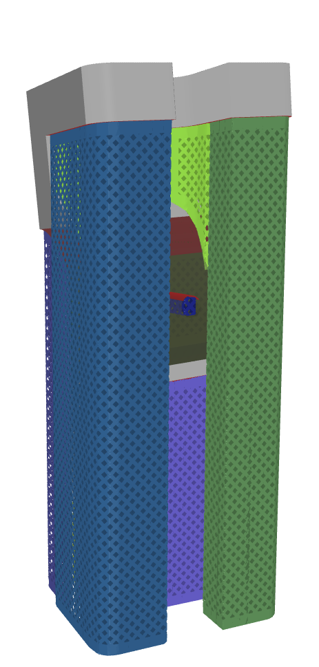
In the Support Structure, the geometry constructed consists of a grid and a boundary which features a polygon derived truss structure in order to support powder removal and control the stiffness of the structure. Below highlights the capability for generated truss-based support structure suitable for PBF process. Carefully observe that individual support blocks are separated when self-intersecting and precisely conform to the original geometry. The support volumes themselves interface with the original part, by performing an exact boolean intersection.
Support Structure Generation in PySLM 0.5 suitable for Selective Laser Melting. Separate support regions are generated for the part using a projection method and a truss based support structure is generated in a grid and along the boundary.
Within the support volumes generating a grid-truss support structure can be generated by taking 2D cross-sections and applying various polygon clipping techniques to generate the structure to create the truss. These trusses structure are particularly more efficient for scanning as these slice as individual scan vectors rather than a series of point exposure.
A view from the bottom showing the grid truss support structure generatedA slice or cross-section taken through both the part and support structures. It can bee seen that the support structure is constructed from a grid which represented single linear scan vectors during scanning.
Future work intends to correctly hatch the support structure regions and integrate a multi-body slice and hatching procedure, but this is intended for inclusion in a future release, possibly PySLM 0.6.
Due to the implementation’s brevity, the proposed methodology will be split across multiple-posts. Anecdotally, work began on a support method over two years ago, intended to offer a more complete input towards deriving a cost model based on existing research in the literature – for further guidance refer to the following posts (Build time estimation).
Background on Support Structures
Support structures are a vital element to Additive Manufacturing. Despite the additional cost of post-processing support structures, these are useful and in some instances essential for successful manufacture of metal AM parts. Most 3D printed users will be very familiar with support generation: the tedious removal of additional structures in most AM processes (FDM, SLM, SLA, BJF, EBM) and the practical difficulty removing this material afterwards. SLS/HSS for polymer parts are largely immune from this manufacturing constraint and make it as a technology for every attractive and cost efficient to produce 3D printed parts without much specific knowledge from the designer. They serve a variety of purposes beyond geometrically supporting overhang surfaces, namely:
Anchor the part onto to the build platform before removal using Spark Erosion or Wire Electric Discharge Machining
Counter-act distortion in materials prone to residual stresses, when compensation factors cannot be used through AM build simulations
Provide a path to dissipate heat to prevent overheating of regions,
Provide structure to support forces exerted during post machining interfaces.
Even with the best intention for the engineer or technician to design these out, it is likely that these may need to be included. On-going development and research to adapt topology optimisation [1][2][3][4][5][6] to support ‘overhang constraints’ or specifically minimise boundaries with support angles that require support has progressed within recent years since the time of this post. Research has also considered using topology optimisation to structurally derive support structures based on an ‘inherent strain’ or distortion as an input [7]. Infact, are now available as design constraints within commercial Topology Optimisation software. However, momentarily these are currently not a complete or holistic solution. By their inclusion, there is a detriment to the overall performance of the solution optimsed. They also do not factor other objective functions such as minimising support material, overhang surfaces, part anisotropy and crucially the piece part cost [8][9]. In industrial applications, the part functionality or fundamental shape may make this challenging or penalise the algorithms. ‘Generative’ approaches, may globally optimise the part (including orientation) to minimise the requirements of support structures, but it is inevitable that some use is required. Geometrically, the quality or surface roughness of overhang or down-skin surfaces are improving through process optimisation of the laser parameters provide by the OEMs. There are indications that the choice of powder size and the layer thickness may improve the surface finish of these problematic regions.
Under some situations support structures can minimise the risk taken to manufacture parts first-time and ultimately reduce the cost of a supplier delivering the part to the customer. It also provides paths to dissipate excess heat generated which will become a further challenge to overcome with the adoption of multiple-laser SLM systems. Research has also proposed different support structures strategies for mitigating the effects of overheating and distortion in the SLM process [10], which included using topology optimisation to find thermally efficient support structures for heat transfer.
Support Structure Generation Capability in existing AM Pre-processing Software
For the specific area of interest for PySLM, it is a particular challenging requirement that remains to be overcome in selective laser melting and to a much lesser extent electron beam melting. The generation of support structures in FDM and SLA technologies is well established and available in consumer-led software for popular FDM printers such as Ultimaker Cura, Slic3r, SLA Formula’s Preform for SLA, or Chitubox for DLP . Fortunately, some of these software are opensource and provide some reference to how these are generated and successfully adopted across FDM 3D printing. Arguably, I have yet to delve into methods for how these are generated but it is expected the supports generated are similar to that used in metal AM . In metal additive manufacturing, commercial capability is available in both Materialise’s Magics SG/SG+ Module, Netfabb and to some existing OEM software. A reference and implementation of support generation for commercial or industrial led 3D printing especially in metal additive manufacturing is currently non-existent. These software are known to be relatively expensive to purchase and maintain.
Support Structure Generation in Research
In academic literature, the use of commerical software for support generation covers a couple of common research areas in the AM Literature including:
Part assessment: part buildability, overhang analysis
Process planning and optimisation: build-time prediction, build volume packing, cost modelling
Distortion and support minimisation: Numerical simulation to minimise distortion and support structure requirements
Lattice structures: minimising support structure requirements
Further overview of current work and research in Support Structures is also reported [11]. Specifically concerning about support generation in Laser PBF processes for these posts, support generation remains an outstanding challenge with the process.
Overhang Areas
Overhang areas are characterised as those prone to generate surfaces that do not conform to the intended geometry of the digital model. These usually result in with surfaces of high roughness / poor surface quality or formation of ‘dross’. These underlying regions may be susceptible to defect inclusions due to the localised overheating, due to the insulative behaviour of powder underneath the exposure zone. Fundamentally, Overhang areas correspond with the build-up of geometry inclined at shallow angles inclined against the build direction i.e. ‘overhang-angle’. It is dependent on many factors including the
machine system,
material alloy processed,
layer thickness,
optimisation of laser parameters (the down-skin parameter set).
Completely unsupported areas – those which do not have any solid material underneath, exasperate this effect. Under some situations, the support material become disconnected and dislodged by the powder spreading or re-coating mechanism, which in the extreme case may cause build-failure.
Mitigating the Effects of Distortion due to Residual stress
Some metal alloys are susceptible to the effects of residual stress generation, in particular Titanium. These stresses manifest with the manufactured part due to thermal-gradients. The effect of residual stress is that it generates internal forces causing distortion of the part. In the extreme situations, it can cause failure due of material due to stresses exceeding the material yield-point. During the build-process, it causes parts to ‘curl’ upwards. This can be somewhat mitigated to an extent using strong enough support structures in the correct place. It can be decided through the intuition the of the machine operator or now through the use of dedicated AM build simulation software. Various research has investigated the optimisation of support structures based on distortion of parts [12].
Much further could be discussed about the area of residual stress in detail but it can be further looked at within the literature. A future post may focus on this in greater detail.
Challenges Created by Support Structures
Amongst post-finishing requirements to achieve required tolerances of a manufactured part it contributes a significant cost to the end-part when they cannot be avoided.
Removal of metal supports is unpleasant and unsatisfactory stage of the manufacturing process. This is dependent on the hardness/strength of the material alloy and the type of supports utilised. They open up the myriad of variability from ‘hand-fettled‘ or ‘artisan’ finishes achieved through support – often referred as the artisanal craft of 3D printing. Even post machining the supports of is an additional process, that requires setup and also the time to prepare the part on the CNC machine. Perhaps, the utilisation of robotic CNC machining in the future will significantly reduce the cost of support removal as part of serial production. It would be fantastic to see some exploration integrating CNC machining of support removal directly from PySLM and is a move towards digital twins.
Support structure contribute the following (in)-direct intrinsic costs for a part produced by metal AM:
Indirect impact on functional performance by designing around overhang constraints
The additional time and cost for the designer to correctly generate the support – including simulation time
The direct cost of building the support structures on the system
The support removal time (machined or hand removed)
Direct impact on the e.g. total performance of the part due to this constraint e.g. surface roughness impacting fluid flow, fatigue performance
Aims of the PySLM Support Module for Support Structures
Support generation capability in PySLM aims to provide a working reference for other researchers to adopt amongst their work. Thus assist researcher’s understand and explore the generation of various types of common support structures employed in AM. Also, it will enable the entire AM ecosystem to have some capability that it can be adapted accordingly for their own wishes.
It does not intend to guarantee to provide a production ready support generation for metal AM parts without careful attention. In the future, this will expand to explore various approaches and further refine capability for PySLM to be a more comprehensive toolbox for use in AM research.
Leary, M., Merli, L., Torti, F., Mazur, M., & Brandt, M. (2014). Optimal Topology for Additive Manufacture: A method for enabling additive manufacture of support-free optimal structures. Materials & Design, 63, 678–690. https://doi.org/10.1016/j.matdes.2014.06.015
Gaynor, A. T., & Guest, J. K. (2016). Topology optimization considering overhang constraints: Eliminating sacrificial support material in additive manufacturing through design. Structural and Multidisciplinary Optimization, 54(5), 1157–1172. https://doi.org/10.1007/s00158-016-1551-x
Garaigordobil, A., Ansola, R., Santamaría, J., & Fernández de Bustos, I. (2018). A new overhang constraint for topology optimization of self-supporting structures in additive manufacturing. Structural and Multidisciplinary Optimization, 58(5), 2003–2017. https://doi.org/10.1007/s00158-018-2010-7
Allaire, G., Bihr, M., & Bogosel, B. (2020). Support optimization in additive manufacturing for geometric and thermo-mechanical constraints. Structural and Multidisciplinary Optimization, 61(6), 2377–2399. https://doi.org/10.1007/s00158-020-02551-1
Zhang, Z. D., Ibhadode, O., Ali, U., Dibia, C. F., Rahnama, P., Bonakdar, A., & Toyserkani, E. (2020). Topology optimization parallel-computing framework based on the inherent strain method for support structure design in laser powder-bed fusion additive manufacturing. International Journal of Mechanics and Materials in Design, 0123456789. https://doi.org/10.1007/s10999-020-09494-x
Brackett, D., Ashcroft, I., & Hague, R. (2011). Topology optimization for additive manufacturing. Solid Freeform Fabrication Symposium, 348–362. Retrieved from http://utwired.engr.utexas.edu/lff/symposium/proceedingsarchive/pubs/Manuscripts/2011/2011-27-Brackett.pdf
Brika, S. E., Mezzetta, J., Brochu, M., & Zhao, Y. F. (2017). Multi-Objective Build Orientation Optimization for Powder Bed Fusion by Laser. Volume 2: Additive Manufacturing; Materials, (August), V002T01A010. https://doi.org/10.1115/MSEC2017-2796
Paggi, U., Ranjan, R., Thijs, L., Ayas, C., Langelaar, M., van Keulen, F., & van Hooreweder, B. (2019). New support structures for reduced overheating on downfacing regions of direct metal printed parts. Solid Freeform Fabrication 2019: Proceedings of the 30th Annual International Solid Freeform Fabrication Symposium – An Additive Manufacturing Conference, SFF 2019, 1626–1640. Austin, Texas, USA.
Jiang, J., Xu, X., & Stringer, J. (2018). Support Structures for Additive Manufacturing: A Review. Journal of Manufacturing and Materials Processing, 2(4), 64.https://doi.org/10.3390/jmmp2040064
Krol, T. A., Zaeh, M. F., Seidel, C., & Muenchen, T. U. (2012). Optimization of supports in metal-based additive manufacturing by means of finite element models. SFF, 707–718.
Determining overhang regions are crucial for detected potential failure points for unsupported regions that are necessary to generate support structures for 3D Printing. Typically, for triangular meshes, this is calculated by taking the dot-product between the triangle normal and the vertical build direction and collecting the values across the entire mesh.
The approach is not particularly complicated. However, depending on some geometries, especially those from topology optimised geometries tend to be have ‘noise’ in the surface triangles, so patches can appear within areas generally considering to require support.
A close-up of an overhang angle showing ‘noisy’ disconnected regions. This is a result of the surfaces slightly above the overhang angle tolerance despite neighbors being under.
One approach taken is using the surface connectivity information to smooth or average the surface normal or overhang angle in order to reduce these discontinuities. The approach taken gathers the adjacent triangle faces and uses the information to identify the overhang angle. This option is enabled when passing the useConnectivity=true argument in pyslm.support.getOverhangMesh (will become available at a later date).
The approach uses the face adjacency information built-into Trimesh’s meshes and collects this in order to map the connectivity between faces. The list of adjacent faces are stored as a Python dict so that they can mapped on-demand.
def getAdjacentFaces(part: Part):
    mesh = part.geometry

    import networkx as nx

    graph = nx.Graph()
    graph.add_edges_from(mesh.face_adjacency)

    adjacentFaces = {node: list(graph.neighbors(node)) for node in graph.nodes}
    return adjacentFaces
Once the facial connectivity is found, each face within the mesh is iterated over. The average overhang angle is calculated accordingly by collecting the faces from the adjacency list into conFaces and then using this to index the numpy array directly.
theta = np.degrees(theta).flatten()
thetaAvg = theta.copy()
adjacencyList = getAdjacentFaces(part)
for face in adjacencyList.keys():
    conFaces = [face] + adjacencyList[face]
    thetaAvg[face] = np.mean(theta[conFaces])
The difference is highlighted below.
Overhang without the connectivity option
Overhang regions identified with connectivity option
Ray Projection Investigation
The support generation – described in this post, builds upon ray projection or ‘ray casting’ method to identify intersecting support areas. The idea was looking at how one could identify supports that are only in contact with the base/build plate – typically acceptable. For reasons later explained, it can be better to work beyond the overhang regions identified based on just the triangular meshes because they can have jagged edges, even with the connectivity approach. It it also not trivial to interpolate across the surface or use polygon offsetting algorithms.
The idea is simple, rays are uniformly distributed and projected underneath the mesh to identify the intercepts with the mesh to find the distance from the build plate. The polygon of the bounding box is generated from the mesh and then is discretised with points using the rasterize function for trimesh.path.Path2D. The rays are projecting using Trimesh’s in-built ray projection facility from the seed points (note: the PyEmbree wrapper library as an auxiliary method does not provide enough accuracy to do this).
# Generate a polygon covering the part's bounding box
offsetPoly  = trimesh.load_path(geometry.generatePolygonBoundingBox(mesh.bounds.reshape(2,3)))

# Rasterise the surface of overhang to generate projection points
supportArea = np.array(offsetPoly.rasterize(resolution, offsetPoly.bounds[0, :])).T

coords = np.argwhere(supportArea).astype(np.float32) * resolution

# Project upwards to intersect with the upper surface
# Set the z-coordinates for the ray origin
coords = np.insert(coords, 2, values=-1e5, axis=1)
rays = np.repeat([upVec], coords.shape[0], axis=0)

#Find the first location of any triangles which intersect with the part
hitLoc, index_ray, index_tri = mesh.ray.intersects_location(ray_origins=coords, ray_directions=rays,multiple_hits=False)
print('\t - finished projecting rays')
The first hit locations with the mesh are stored and the heights are then transformed back to a height-map based on the original bounding-box and resolution used.
The height or depth map (projection) along Z-Direction from the ray projection method
From the height map, the gradients are calculated using 1st order difference stencil within Numpy’s np.gradient function, along each direction. The magnitude is found and the overhang angle is calculated based on the resolution.
Once the angle is obtained the projected overhang regions can be found using the Marching Square algorithm built into Scikit Image (skimage.measure.find_contours). The isolevel chosen is based on the overhang angle and the resolution chosen alongside some carefully selected fudge-factor. A mask is used to remove areas in the background (non-hit areas) based on the background
The projected overhang (45°) region for a topology optimised bracket overlaid on the height map found using ray projectionThe projected overhang region (45°) isolevel overlaid on the calculated overhang angle
The benefits of this approach are not immediately apparent. However, the contour information can be used and smoothed when projecting supports back onto the part. The limitation with the approach is that the projection’s resolution is determined by the overhang angle captured and obviously is based on the line of sight – so any self-intersecting supports with the part are neglected. The approach can be further explored using GLSL shaders in order to remove the bottleneck of ray tracing and achieve the same result.
This method is included as a utility function (pyslm.support.generateHeightMap) and both functions will be made later available with the introduction of the support module.